↓ Up to 95% reduction in measurement program preparation time ↓ Dramatically higher measurement operation efficiency
↓Stable measurement quality ↓Intuitive operations
To increase the efficiency of measurement operations, take a close look at the design process.
Just adding tolerance information to 3D CAD models makes the "one-click"
generation of measurement models by "MiCAT Planner" possible. Safe up to 95 per cent time with our ground-breaking CMM measurement program generation software.
Measurement program preparation time
cut by up to 95%
What took 45 to 60 minutes with a traditional "2D diagram" manual method and 15 to 20 minutes with a "2D diagram + 3D CAD" method, can now be completed in approximately 3 minutes using MiCAT Planner.
Sample block measurement part program preparation time comparison

Measurement possible in the minimum time;
dramatic increase in measurement operation efficiency
What took 45 to 60 minutes with a traditional "2D diagram" manual method and 15 to 20 minutes with a "2D diagram + 3D CAD" method, can now be completed in approximately 3 minutes using MiCAT Planner.
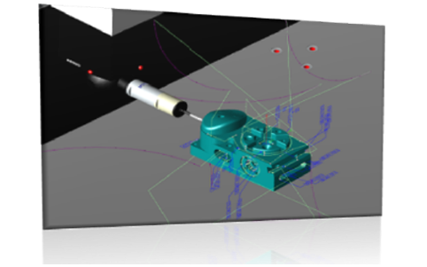
Automatically optimized measurement path
Using optimisation functions, the smallest number of probe-position and tool changes and the shortest measurement path are determined by the software, and a program is generated for the measurement in the minimum amount of time.

By shortening measurement time,
large measurement operation efficiency
gains are possible!
Stable measurement quality with no variations between workers
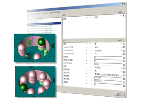
By defining measurement rules using the rules editor function, you can automatically generate a measurement path conforming to those rules. This prevents quality variations between programmers.
Eliminate variations in measurement quality
By defining measurement rules, you can automatically generate a measurement path conforming to those rules, so there are no variations between programmers.

Intuitive operations; easy-to-use simple view
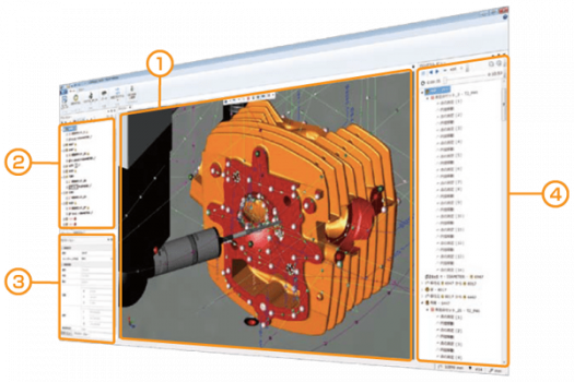
The MiCAT Planner screen configuration provides a "simple view" configuration that enables intuitive operations (3D view, plan view, etc.). You can also freely customise positioning and window size.
Screen configuration and functions

Screen configuration and functions
| ① 3D view | Graphical information is displayed. ・Measuring device information ・CAD models, tolerance information ・Measuring points, measurement path ・Measuring animation |
| ② Plan view | ・Display list of measuring elements, tolerances, etc. ・The existence of measurement and evaluation can be selected using a check box. |
| ③ Property view | Element, tolerance, and measuring point name changes and measuring point editing can be done for each individual element. |
| ④ Program view | ・Display measurement details and projected measurement times. ・Using the animation function, it is possible to execute a 3D-view measurement animation. |
Supported CAD formats
| CAD formats | Extension | Supported versions |
| ACIS | .sat | R1-2016.1.0 (PMI not supported) |
| STEP | .step/ .stp | AP203, AP204, AP242 (PMI not supported) |
| NX *1 | .prt | 11-18, NX1-10 |
| Creo Parametric (Pro/E) *1 | .prt/ .prt.* | 16-Wildfire5, Creo 1.0-3.0 |
| CATIA v5 *1 | .CATPART | v5 R8 – 5 – 6R2016 |
| Solid Works *1 | .sldprt | 98 - 2016 (with PMI: 2014 - 2016) |
*1 Option (One of the types is included as standard.)
Note: The model needs to be a solid model. Assembly data not supported.
Supported MCOSMOS (MiCAT Planner v1.5)
- ①MCOSMOS installed for use in generating programs from MiCAT Planner
MCOSMOS v4.0R9 or later, or MCOSMOS v4.1R6 - ②MCOSMOS installed for use in program execution (repeat mode)
MCOSMOS v4.0R5 or later*To use the measurement programs generated by MiCAT Planner, separate "Execution Rights (Run Option)" are necessary.
"Execution Rights (Run Option)" for one 3D measurement device are included with MiCAT Planner.
【15 languages supported】
Japanese, English (US/UK), German, French, Spanish, Portuguese, Italian, Chinese (simplified/traditional), Korean, Polish, Czech, Dutch, Turkish
Would you like to find out more about our Smart Factory solutions?
Please fill in the form – it will help us to handle your product or service inquiry more efficiently.
Send us your inquiry